|
|
| About S scripts collection |
S scripts collection are tools developed by Raffaele Schiavullo to optimize some processes of the production pipeline.
For any enquiry or update please contact the author at following links:
|
|
|
| |
| Index (click on the icons to jump to the related help section) |
| |
|
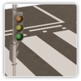 |
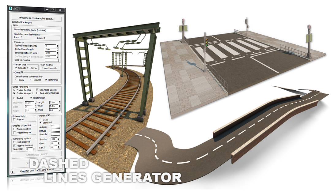
Dashed lines generator is a tool to automate, in few and easy steps, the generation of all types of dashed lines: it can be used to simulate the traffic signs standards; with the SKIN MODIFIER option it is extremely easy to manipulate the dashed lines created, changing their placement and orientation. With this script the user can have an interactive creation process of the dashed line, with a real time preview into the 3DS Max viewports. Features included: |
|
- Interactive update: visualize the dashed lines during the interactive creation process
- Apply skin modifier: automatically apply the SKIN MODIFIER to the dashed lines created, allowing the user to modify the curves after the geometry has been generated
- Vertex type: generate dashed lines with "smooth" or "corner" vertexes
- Clone options: clone the reference spline in" copy", "instance" or "reference" mode
- Lines rendering: interactively change the section and the thickness of the dashed lines during the interactive creation process
- Material: automatically apply VRay or Standard Materials
- Rendering options: interactive set up for the "cast shadows", "receive shadows" or "object ID" properties
- Display properties: change in real time the "freeze", "display as box" and "frozen in gray parameters"
- UK Gov signs manual: a direct link to the pdf file "UK Traffic Signs Manual chapter 5".
|
|
|
 |
|
|
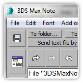
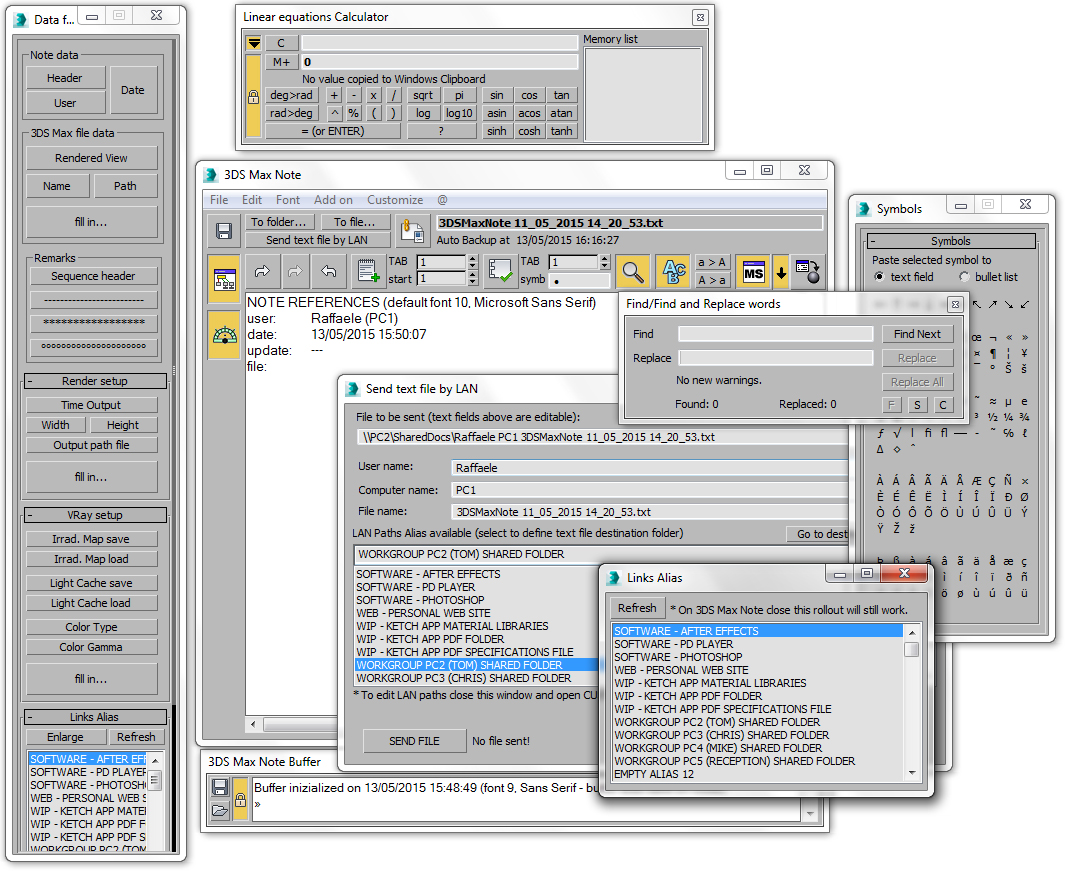
3DS Max Note is an internal text editor to generate .txt documents to share with the members of the working team and it is optimized to compile complex text files to backup projects; furthermore it includes the following extra tools: |
|
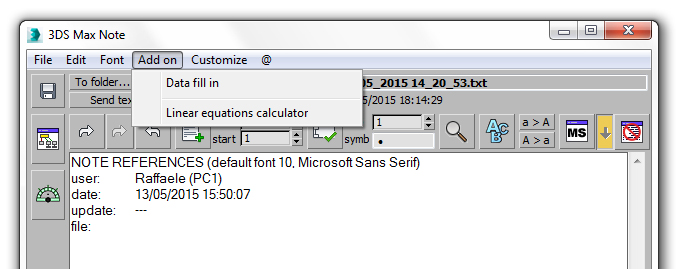
- Linear equations calculator: with this calculator it is possible to solve complex linear equations
(ex. 2+(45*4)-sqrt(34)+log10(23)+(sin(45)/tan(79)))
- Microsoft Word tools: text formatting, numbered lists, bullet points lists, find and replace words, find and enumerate words, characters counter, convert selection to upper or lower case, special symbols list
- VRay and Default Scanline Renderer set up pre formatted parameters: to collect info about the work in progress
- Links alias list window: an internal 3DS Max links collector to open all types of files or folders from 3DS Max
- Send text file by LAN: a window to share file content with the other members of the team with a single click
- Note buffer: extra text editor window to backup user selected text or save the undo actions and reuse the text content later into the main 3DS Max note window, for further elaborations
- Remarks headers: auto compile different headers including some extra info as user name, file name and location, rendered view, saved file, etc.
- Auto backup functions: automatically save text contents on 3DS Max close, on 3DS Note close or on timer set up.
|
|
|
 |
This script will open an auto resizable bar that is possible to place on top of 3DS Max window; it contains the following tools to enhance the following 3DSD Max functions: |
|
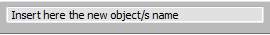
- Extra size name text field: displays the name of the selected object or counts the objects number of a multiple objects selection, solving the problem of the extremely small standard 3DS Max name field
- Resizable pop up extra size name text field: an extra horizontally resizable window to display extra long objects names, extremely useful to work with CAD models imported in 3DS Max with long names generated from exporting processes or laser scanning software
- Warning bar: the red color of the bar, will indicate if the selected object or multiple selected objects have been transformed by the MOVE, ROTATE or SCALE tools; it is extremely useful to prevent accidental transformations (ex. accidental translation of the camera when the user click into a viewport to switch the view)
- Auto rename objects text field: without use the standard 3DS Max rename tool window, it is possible to assign multiple objects names with an incremental index
- Unique name/Multiple names button: with this button the user can assign to the selected objects or to a multiple objects selection a unique or a duplicate name; extremely useful to create an objects name database without duplicated instances, to use to develop code into an external software or code editor
- Floating UNDO/REDO window
- UNDO/REDO text field: read in real time the undo/redo actions performed without opening the standard 3DS Max undo/redo list
- Copy and paste tool: copy and paste name and wire colors between objects or selection sets.
|
| |
|
|
|
|
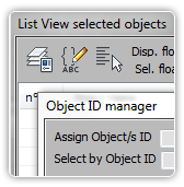 |
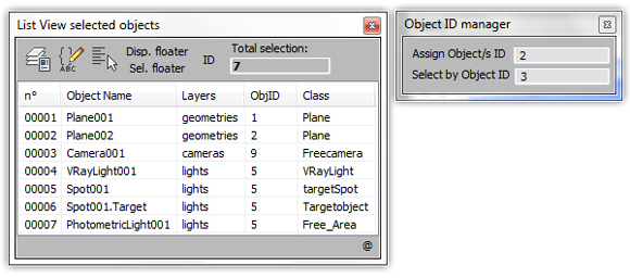
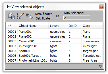
It is a dockable window that collects all the 3DS Max selection methods and a table that displays some properties for the selected objects: it is suitable to be used to easily identify on which layers the objects are located, the class and the objects ID; it contains the OBJECT ID MANAGER tool and the following features and links: |
|
- Quick links: collection of buttons to open all the 3DS Max selection methods (Layer Explorer, Named Selection Sets, Select form Scene, Display floater, Selection Floater)
- Selection order: listed into the objects list, it shows to the user the exact selection order of the objects, that is extremely important for the dynamic simulations
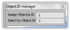
- OBJECTS ID MANAGER: select the elements into the scene by object ID or assign an Object ID to a single or multiple selection without open the "Objects properties window" by the quad menu
- OBJECTS LIST: contains objects properties (selection order, objects names, layers, Object ID, class).
|
 |
|
| |
|
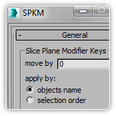 |
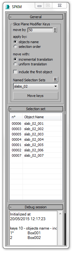
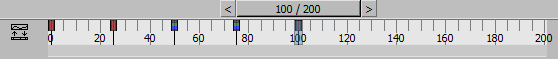
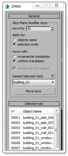
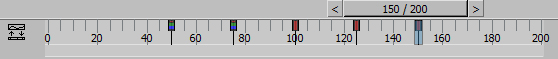
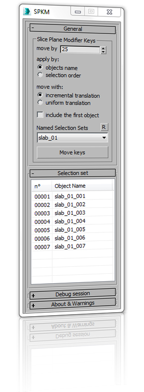
This tool has been developed to speed up the animation process for architectural phasing when a repetitive sequence is required (ex. phasing animation for skyscrapers, steel frames structures, etc.). It allows the user, with only one action, to shift the animation keys of the slice planes modifiers applied to different geometries with an incremental or uniform value: the translation can be serialized by a selection order or by objects name. The tool contains the following sections and options: |
|
- Move by: the shift amount of animation keys for the slice planes modifiers to apply to the selected objects; this value can be positive or negative
- Apply by objects name: the shift sequence for the animations keys of the slice plane modifiers applied to the selected objects will be executed by objects name
- Apply by selection order: the shift sequence for the animations keys of the slice plane modifiers applied to the selected objects will be executed by selection order
- Move with incremental translation: starting from the first objects into the selection, an incremental translation of the animation keys for the slice plane modifiers will be applied (if "move by= 10" and 3 objects with the slice planes modifiers applied and animated are selected, the first object into the selection will have a translation of the animation keys of 10 frames, the third one of 30 frames)
- Move with uniform translation: to all the objects into the selection, a uniform translation of animation keys for the slice plane modifiers animated will be applied (if "move by= 10" and 3 objects with the slice planes modifiers applied and animated are selected, all the objects into the selection will have a translation of the animation keys of 10 frames)
- Named selection set: the user can create selection sets to easily select geometries and apply the transformation
- Selection set list: it is a list with the selection order made by the user
- Debug session: after the shift of the keys has been applied to all the objects, the user can check into this rollout if all the processes have been executed correctly and what types of errors the script has generated for each single geometry selected.
|
|
| |
|
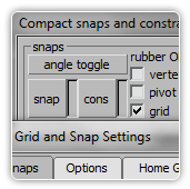 |
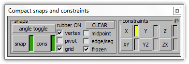
This is a compact version of the default window "Grid and Snap settings" to use during massive modeling sessions, without taking too much space on the screen; it has a built in function that automatically activates the "Display rubber band" option when the user press the "snap" button. Furthermore there is a "constraints section" to easily switch between all the possible options. Clicking the right mouse button on the "snap" or "constraints" buttons, will open the default window "Grid and Snap settings". All the changes into this window will affect the default window "Grid and Snap settings" and vice versa. |
|
- Right mouse button: clicking the right mouse button on the "snap" or "constraints" buttons, will open the default window "Grid and Snap settings"
- Display rubber band:there is a built in function that automatically activate the "Display rubber band" option when the user press the "snap" button.
|
| |
 |
|
|
| |
|
| |
| |
|
|
| |
|
| |
|
 |
|
| |
| Dashed lines generator is a tool to automate, in few and easy steps, the generation of all types of dashed lines: it can be used to simulate the traffic signs standards; with the SKIN MODIFIER option it is extremely easy to manipulate the dashed lines created, changing their placement and orientation. With this script the user can have an interactive creation process of the dashed line, with a real time preview into the 3DS Max viewports. |
|
 |
|
| |
| How to install |
|
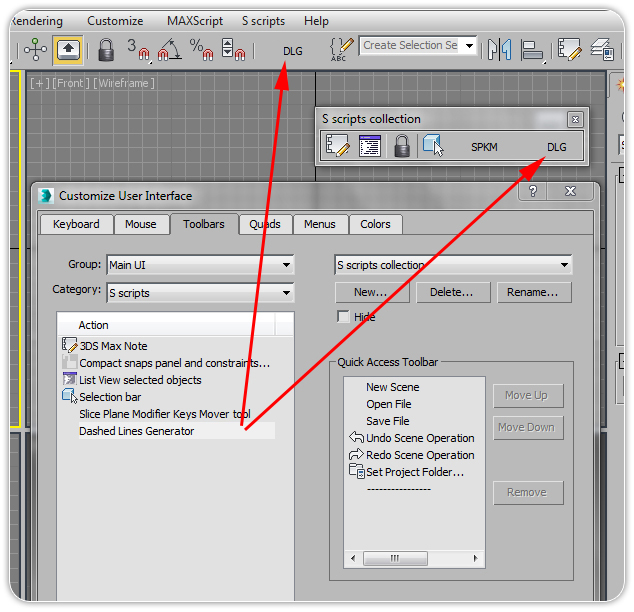
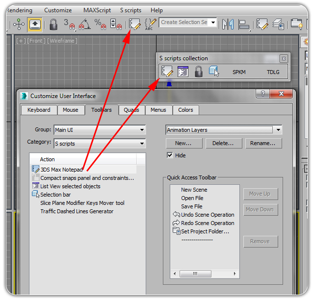
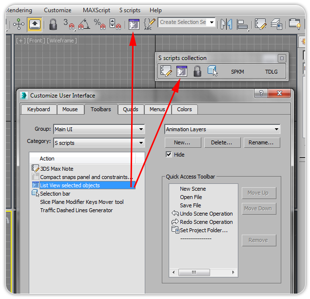
- Drag the file from the folder where it is located directly into one of the 3DS Max viewports; the script will automatically create a category named "S Scripts"
- Go to CUSTOMIZE > CUSTOMIZE USER INTERFACE > TOOLBARS and into the sub menu CATEGORY from the related drop down list select "S Scripts"
- Fom the list ACTION select the item named "Dashed Lines Generator" and drag it directly to 3DS Max Main Tool Bar and a button withthe label "DLG" will be added to it.
For more detailed instructions on how to install a script click here.
For more detailed instruction on how to create a new tool bar click here. |
 |
|
| |
|
| How it works - Main window
|
|
| |
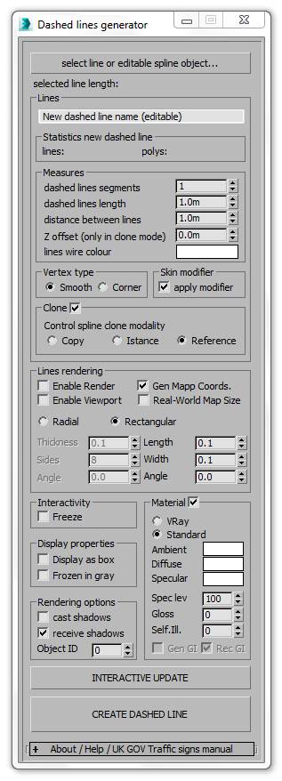 |
To generate a dashed line, the user simply needs to select a spline or an editable spline into the scene to be used as path, applying the roll outs parameters. |
| With this script the user can have an interactive creation process of the dashed line, with a real time preview into the 3DS Max viewports; please refer to the option INTERACTIVE UPDATE to learn how to activate this feature. |
 |
|
| |
The following features are excluded from the interactive creation process, but will be applied when the button "Create Dashed Line" is pressed: Skin modifier, Freeze, Display as box, Frozen in Gray, Cast shadows, Receive Shadows, Gen GI, Receive GI.
Into the "Above" roll out there is a direct link to the pdf file "UK Traffic Signs Manual chapter 5".
- Select line or editable spline object: click to select a compatible object into the scene (only line or editable splines are accepted) to use as path to generate the dashed line
- New dashed line name: these text filed is editable; if no changes are made, the new dashed line will be automatically renamed (ex. if the name of the selected shape is Line001, the new dashed line will have this name Line001__dashed_linexxx; each new dashed line will have a unique name into the scene)
- Selected line length: after the user has selected a compatible object into the scene, this label will indicate the length of the element in word units (Meters, inch, etc.)
- Statistics new dashed line: it will indicate the number of lines and polygons generated by script
- Dashed lines segments: this value defines the number of segments that each line element contains (ex. if in the Statistics Group "lines=5" and "dashed lines segments=3", then the dashed line will contain 5*3= 15 segments)
- Dashed lines length: the length of each element of the dashed line
- Distance between lines: the distance between the end of a segment and the beginning of the next one
- Z offset: this parameter is available only when the Clone option is on; it will indicate the translation (positive or negative) along the Z axis of the cloned line or spline
- Lines wire colour: the wire frame colour of the dashed line created by the script
- Vertex type: set the vertex type for each dash of the line created by the script
- Skin modifier:when on, the script will create the dashed line and then will apply to it the SKIN MODIFIER to easily manipulate it, changing its placement and orientation: the modifier will be applied only after that the user has pressed the "CREATE DASHED LINE" button and not during the set up process.
This "skin modifier" option is available only if the selected line or editable spline is made by 1 sub-object spline, if not the following warning message will be prompted:
"The selected shape has more than 1 spline sub-object: the script will work properly, but it won't be possible to apply the skin modifier to the dashed line created. To apply the skin modifier, the selected line or editable spline must have only 1 spline as sub-object."
To apply the skin modifier, the script works in two different ways, depending on the Clone section.
When skin modifier is on and Clone section is off, the script will automatically rename the selected spline (ex. if the name of the selected shape is Line001, it will be renamed as Line001__control_spline and will create a new dashed line named Line001_ dashed_line001)
When skin modifier is on and Clone section is on, the script will automatically rename the selected spline (ex. if the name of the selected shape is Line001 and Clone option is set to "reference", the script will generate the following splines: Line001_reference_control_spline001, Line001_reference_dashed_line001).
- Clone: when this section is on, the script will generate a clone of the selected shape and will rename it (ex. if the name of the selected shape is Line001, the cloned line will have one of the following names depending from the option chosen: Line001_copy_dashed_linexxx, Line001_istance_dashed_linexxx, Line001_reference_dashed_linexxx; each cloned element will have a unique name into the scene).
- Lines rendering: this group contain all the standard parameters included into the roll out "Rendering" for a line or editable spline object (click here for a detailed description).
- Freeze: if on, after that the user has pressed the "Create Dashed Line" button, the new dashed line created will be frozen.
- Display as box: when on, after the user has pressed the "Create Dashed Line" button, the new dashed line will be displayed as a box
- Frozen in gray: when on, after the user has pressed the "Create Dashed Line" button, the new dashed line will be displayed in gray colour if the option "Freeze" is on
- Cast shadows: when on, the new dashed line cast shadows.
- TIP: leave it off and the dashed geometry will not casts shadows, as a real painted dashed line
- Receive shadows: when on, the new dashed line receive shadows.
- TIP: leave it on and the dashed geometry will receive shadows, as a real painted dashed line
- Object ID: Setting Object ID to a nonzero value means that the object will receive the rendering effects associated with that channel in Render Effects and the post-processing effects associated with that channel in Video Post
- TIP: to save the channel data with the rendering, render to either the RLA or RPF file format.
- Material: when on, a material will be applied to the new dashed line; if VRay is not installed or it is not assigned as default renderer, a warning message will be prompt. For a detailed overview about "standard material" click here.
- Gen GI: (available only with VRay material) when on the new geometry will generate GI
- TIP: leave it off, to avoid rendering problems when the dashed line created is too near the ground.
- Rec GI: (available only with VRay material) when on the new geometry will receive GI
- when the button "INTERACTIVE UPDATE" is pressed, the user will have a real time preview of the dashed line he is creating into the 3DS Max viewports; it is possible to switch on or off this button in each moment of the creation process. If on, the button will be automatically switched off when the button "Create Dashed Line" is pressed.
- TIP: activate this button during the creation process to understand if the set up of the parameters for the new dashed line is correct
- Create Dashed Line: when pressed the script will create the dashed line basing on user set up.
|
| |
| |
|
|
| |
|
| |
|
| |
|
|
| |
| Overview |
|
3DS Max Note is an internal text editor to generate .txt documents to share with the members of the working team and it is optimized to compile complex text files to backup projects.
The following image shows all the tools that 3DS Max Note include. |
|
| |
|
| How to install |
|
- Drag the file from the folder where it is located directly into one of the 3DS Max viewports; the script will automatically create a category named "S Scripts"
- Go to CUSTOMIZE > CUSTOMIZE USER INTERFACE > TOOLBARS and into the sub menu CATEGORY from the related drop down list select "S Scripts"
- Fom the list ACTION select the item named "3DS Max Notepad" and drag it directly to 3DS Max Main Tool Bar and a button with an icon will be added to it.
For more detailed instructions on how to install a script click here.
For more detailed instruction on how to create a new tool bar click here.
|
 |
| |
|
| How it works - Configuration File and Dummy File |
|
| |
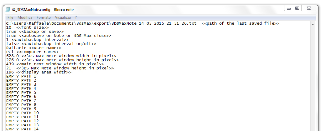
When 3DS Max Note is initialized, it will automatically generate the following files into the default folder C:\Users\UserName\Documents\3dsMax\export\
- configuration file named @_3DSMaxNote.config
- dummy file named @_3DSMaxNote_Dummy.config
- the first .txt file named 3DSMaxNote_date_time.txt
- the first .txt backup file named3DSMaxNote_date_time_backup.txt
- the first .txt auto backup file named 3DSMaxNote_date_time_backup_auto.txt
1. This file will be updated each time that the user will change the 3DS Max Note Settings, update the "Links List", update the "Links Alias List" or save a file: it's possible to edit the file manually by a text editor. Please refer to the following sessions for details How it works - main window - Customize menu and How it works - configuration file repairing process: do not change the file location or delete it.
2. The dummy file is used by 3DS Max Note for his initialization and in case of errors: do not change the file location or delete it.
3. The first .txt file named 3DSMaxNote_date_time.txt is used to initialize the configuration file @_3DSMaxNote.config, this file can be deleted in case of need
4. The first .txt backup file named 3DSMaxNote_date_time_backup.txt is used to initialize the configuration file @_3DSMaxNote.config, this file can be deleted in case of need; this file is generated because the option "Backup on save" is default on. Please refer to the section Customize menu for details.
5. The first .txt auto backup file named 3DSMaxNote_date_time_backup_auto.txt is used to initialize the configuration file @_3DSMaxNote.config, this file can be deleted in case of need; this file is generated because the option "Auto back up interval" is default on. Please refer to the section Customize menu for details. |
| |
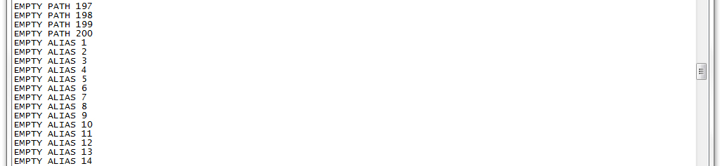
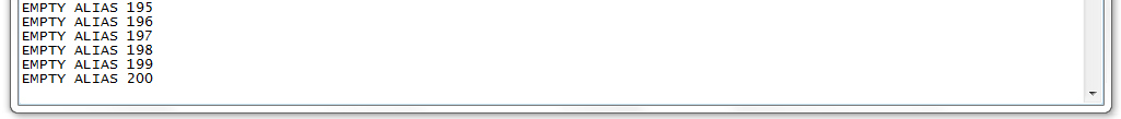
| This is an example of a standard configuration file edited by Windows Note. |
|
| |
|
| How it works - main window - File menu |
|
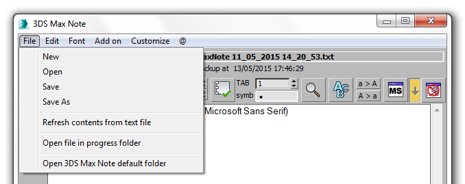 |
- New: create new .txt file
- Open: open file; each time that 3DS Max Note is open, it will automatically load the last saved file.
 Save: save file Save: save file
- Save as: save the current file with a different name
- Refresh content from text file: if two users are working on the same file, this option will update the content of the text window from the last saved file
- Open file in progress folder: open the folder in which the file in progress is saved
- Open 3DS Max Default folder: open the folder in which is located the configuration file automatically generated by the script when it starts for the first time; the default path is C:\Users\UserName\Documents\3dsMax\export
|
| |
|
|
|
| How it works - main window - Edit menu |
|
|
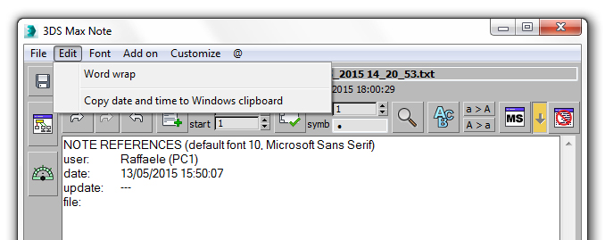 |
- Word warp: warp the words into the text window to let the user use only the vertical scroll and disable the horizontal scroll
- Copy date and time to windows clipboard: copy date and time to windows clipboard to be past into another software or text editor
|
| |
|
|
|
| How it works - main window - Font menu |
|
|
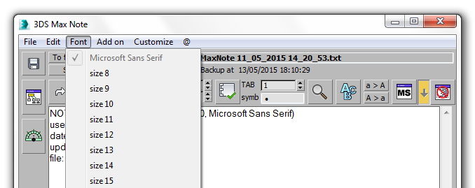 |
- Font: set the size of the default font
|
| |
|
|
|
| How it works - main window - Add On menu |
|
|
 |
|
| |
|
|
|
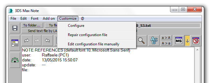
| How it works - main window - Customize menu |
|
|
 |
|
- Configure: open the configuration window named"Configure 3DS Max Note"
- Repair configuration file: this option will run a routine to repair the configuration file @_3DSMaxNote.configlocated in C:\Users\UserName\Documents\3dsMax\export; use the process in case of problems to start 3DS Max Note or your Links List is damaged. Refer to Configuration file repairing process session for details
- Edit configuration file manually: the configuration file @_3DSMaxNote.config is editable by a text editor; with this option 3DS Max Note will try to open it.
To edit the configuration file properly the file extension .config must be associated with a text editor: save the edited file with the same extension (.config), otherwise 3DS Max Note will prompt the following message and will automatically repair the configuration file, overwriting the user settings:
"There has been an error since your last opening or you have repaired the configuration file, then the Dummy file has been loaded. Load your file manually by File>Open menu"
|
| |
|
|
|
| How it works - Configuration file repairing process |
|
|
| |
|
| The repairing process activated by the option "Repair configuration file" will delete the existing @_3DSMaxNote.config file to create a new one and consequently will delete all the user links too: the process in not undoable; to backup the links list before starting the process, try to manually open the file with a text editor and copy the contents needed. At the end of the repairing process, it will be possible to paste the copy contents into the new generated file. |
| |
|
| This is an example of a standard repaired configuration file; in case of need, edit it by a standard text editor and save it with the extension .config |
|
| |
|
|
|
| How it works - Configuration window
|
|
|
| |
|
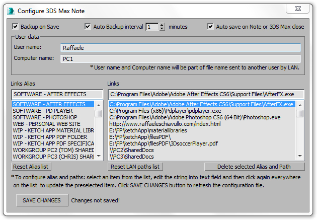 |
- Backup on save: when on, 3DS Max Note will create a copy of the saved file into the same folder (ex. if the file name is Demo_file.txt, the backup file name will be Demo_file_backup.txt)
- Auto Backup interval: when on, 3DS Max Note will create a copy of the text file in progress every "n" minutes into the same folder (ex. if the file name is Demo_file.txt, the auto backup file will be named Demo_file_backup_auto.txt and will be overwritten at each saving)
- Auto save on Note or 3DS Max close: when on, the text file in progress will be automatically saved on 3DS Max Note close or on 3DS Max close, to prevent data loss.
- User Name: the value of this text field is editable and its initial content is grabbed from the Windows User Name; it will be used to auto compile the name of the text file in progress, when it is sent to another working group user (refer to SENT TEXT FILE BY LAN section)
- Computer Name: the value of this text field is editable and its initial content is grabbed from the Windows Computer Name; it will be used to auto compile the name of the text file in progress, when it is sent to another working group user (refer to SENT TEXT FILE BY LAN section)
- Links Alias: this list works as a BOOKMARKS LIST and it is linked to the "Links List" on the right side of the same window; the list contain 200 rules to be filled with links.
Go to the configuration process to learn how to configure this list.
|
| |
- Links List: refer to Links Alias
- Reset Alias List: will reset the content of the list; click on "SAVE CHANGES" button to update the configuration file @_3DSMaxNote.config; until then no changes will be saved
- Reset LAN paths list: will reset the content of the list; click on "SAVE CHANGES" button to update the configuration file @_3DSMaxNote.config; until then no changes will be saved
- Delete selected Alias and Path: use this button to delete an element in both lists; select the element to delete in one of the lists and press the button: the selected element and the correspondent one will be deleted and both lists will be update. To save changes into @_3DSMaxNote.config, press on "SAVE CHANGES" button.
- Delete selected Alias and Path: use this button to delete an element in both lists; select the element to delete in one of the lists and press the button: the selected element and the correspondent one will be deleted and both lists will be updated. To save changes into @_3DSMaxNote.config, press on "SAVE CHANGES" button.
- SAVE CHANGES: press this button to save user changes to this window and update the configuration file @_3DSMaxNote.config.
|
|
|
| |
| How to configure the "Links Alias List" and the"Links List" windows |
|
The "Links Alias List" works as a BOOKMARKS LIST and it is linked to the "Links List" on the right side of the same window. To configure the "Links Alias List", open the Configuration Window and select an item from the first list, edit the string into the text field and then click again everywhere on the same list to update the compiled item; the script will select the corresponding numbered item into the "Links List" and then will be possible to edit this field too by the top text area of the "Links List".
When the changes are made, click on "SAVE CHANGES" button to save them into the configuration file @_3DSMaxNote.config; until then no changes will be saved.
All the "Links Alias List" contents will be converted into capital letters and organized by alphabetical order.
With this procedure is possible to create a BOOKMARKS LIST containing each kind of link to the projects files (and not only...give a look to the picture!), to be used by the windows LINKS ALIST LIST WINDOW  and "SEND TEXT FILE BY LAN". and "SEND TEXT FILE BY LAN".
The script accept each kind of link: files, software (.exe), web pages, images, etc. |
|
|
| |
| How it works - Links Alias List window |
|
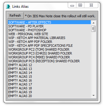 |
Press to open Links Alias List Window.
The list contains 200 rules to be filled with links.
This window is a BOOKMARKS LIST created and updated by the user following this configuration process by the Configuration Window.
When changes are made by the Configuration Window click  to update Links Alias List content. to update Links Alias List content.
Double click on items list to open the link associated with it. |
| |
|
| |
|
|
|
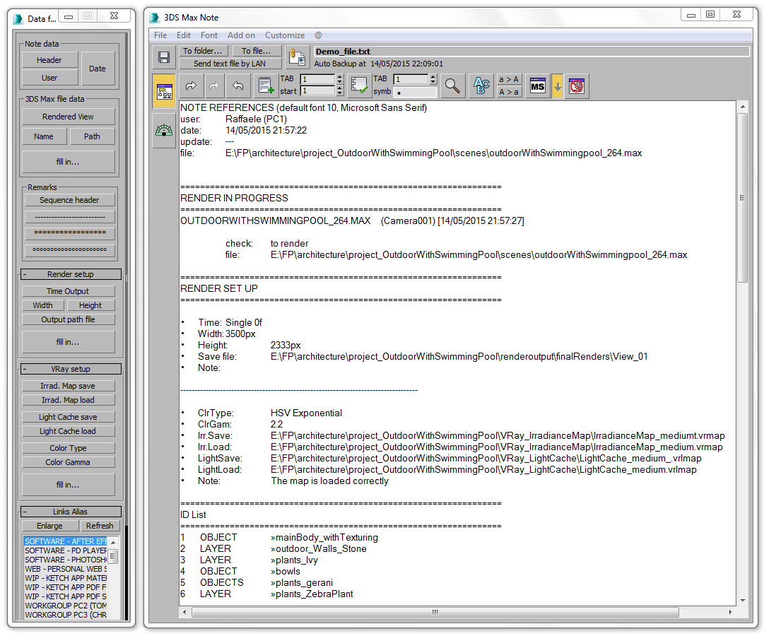
| How it works - Data Fill In window overview |
|
| |
|
| This window contains the section of 3DS Max Note dedicated to the backup of the projects and it is suitable to be used during the working process to keep records of the work in progress. The following image is an example of a file formatted during the making of a complex project for architectural visualization, using the format commands of the "Fill in window". |
| |
 |
| |
|
|
|
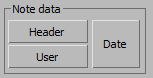
| How it works - Data Fill In window - Note Data |
|
|
| |
|
|
- Header: will automatically fill the main text window with the following data, where the field user is obtained combining the active user name and the net name of the workstation and the field file is grabbed from the scene open in 3DS Max
- User: will automatically fill only the field user
- Date: will automatically fill only the field date with the current time too.
|
| |
 |
| |
|
| |
|
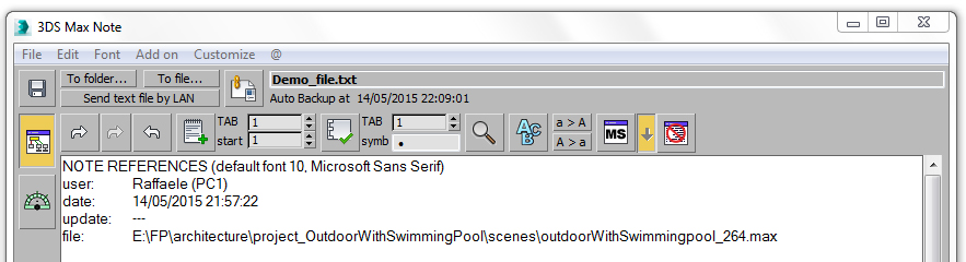
| How it works - Data Fill In window - 3DS Max File Data |
|
|
| |
|
|
- Fill in: will automatically fill the main text window with the following data, where:
- Rendered View is the last rendered user camera
- Name in capital letters, is the scene loaded into 3DS Max
- Path is the user path to save the loaded scene into 3DS Max
- Rendered View: will automatically fill only the rendered view name
- Name: will automatically fill only the file name field in capital letters
- Path: will automatically fill only the path field of the 3DS Max scene loaded.
|
| |

|
| |
|
|
|
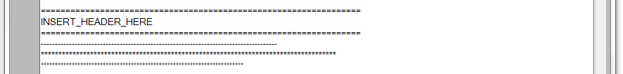
| How it works - Data Fill In window - Remarks |
|
|
| |
|
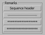 |
- This section contains 4 different markers to automatically format different remarks into the main text window.
|
 |
|
| |
|
|
|
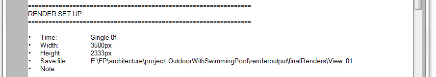
| How it works - Data Fill In window - Render Setup |
|
|
| |
|
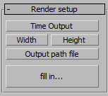 |
| This roll out will works properly only if one render is started (but not finished) or has been made, because until then, 3DS Max will not generate the values of the TIME OUTPUT configuration into the RENDER SET UP window. |
- fill in: will automatically fill the main text window with the following data, where:
- Time Output is a values depending from the user TIME OUTPUT configuration into the RENDER SET UP window:
- Active Time segment (interval xf xxf)
- Range xf-xxf
- Frames x,y,w-z
- Width is the value of the last rendered frame window
- Height is the value of the last rendered frame window
- Output path file is the user path to save the last render
- Time Output: will automatically fill only the range of rendering
- Width: will automatically fill only the width value of the rendering rendered frame window
- Height: will automatically fill only the height value of the rendering rendered frame window
|
 |
|
| |
|
|
|
| How it works - Data Fill In window - VRay Setup |
|
|
| |
|
 |
| This roll out will works properly only if Vray is the current renderer, otherwise a warning message will be displayed. |
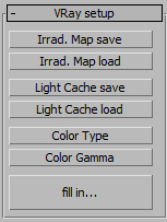
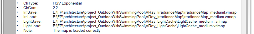
- fill in: will automatically fill the main text window with the following data, where:
- ClrType is the user color type algorithm from VRay Color Mapping rollout
- ClrGam is the user Gamma value from the VRay Color Mapping rollout
- Irr.Save is the user path to save irradiance map file
- Irr.Load is the user path to load irradiance map file
- LightSave is the user path tosave the light cache file
- LightLoad is the user path to load the light cache file
- Note is an empty filed that the user can compile manually.
- Irrad. Map save: will automatically fill only the path of the saved irradiance map
- Irrad. Map load: will automatically fill only the path of the loaded irradiance map
- Light Cache save: will automatically fill only the path of the saved light cache map
- Light Cache load: will automatically fill only the path of the loaded light cache map
- Color Type: will automatically fill only the kind of color type algorithm from VRay Color Mapping rollout
- Color Gamma: will automatically fill only the gamma value from VRay Color Mapping rollout.
|
 |
| |
|
|
|
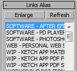
| How it works - Data Fill In window - Links Alias |
|
|
| |
|
|
This roll out is the compact version of the Links Alias List window, please refer to its section to learn how it works and how to populate the list of links.
- Enlarge: this button has the same function of and open the Links Alias List window.
- Refresh: update the contents of the list.
|
| |
|
|
|
|
| How it works - To file / To Folder / Sent text by LAN buttons |
|
| |
|
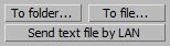
- To folder: open the folder where the text file in progress is saved
- To file: open the text file in progress with the default Windows text editor
- Sent text file by LAN: open the "Sent text file by LAN window" to share the text file in progress with the other elements of the working group.
|
|
| |
|
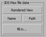
| How it works - Sent text file by LAN window |
|
| |
|
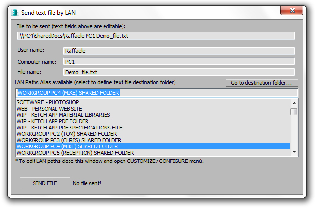 |
Pressing the button  the user will have the access to the " Sent text file by LAN" window and will able to share with the other users into the working group the content of the text file in progress. the user will have the access to the " Sent text file by LAN" window and will able to share with the other users into the working group the content of the text file in progress.
In the image above has been selected "WORKGROUP PC4 (MIKE) SHARED FOLDER" alias and the script has automatically compiled the editable text area "File to be sent" combining all the other data (User Name, Computer name, File name) with the network path linked to the selected alias.
Pressing the "SEND FILE" button, a copy of the text file in progress, will be saved into the destination folder; in this case the file named Demo_file.txt will be saved into the "Shared Folder" on the PC4 of the user Mike.
All the text fields into this window are editable.
- File to be sent: this text area will be auto compiled each time that the user change the contents into the other text field of the windows, or when they select an item from the LAN Paths Alias list
- User name: this value is loaded from the configuration file @_3DSMaxNote.config and it can be edited into this window, but the changes will be not saved; please refer to Configuration window to permanently configure the User Name
- Computer Name: this value is loaded from the configuration file @_3DSMaxNote.config and it can be edited into this window, but the changes will not be saved; please refer to Configuration window to permanently configure the User Name
- File name: this value is loaded from the configuration file @_3DSMaxNote.configand it can be edited into this window, but the changes will not be saved; to change it permanently, the current text file must be saved with another name with the command "Save As"
- Go to destination folder: on press will be open the folder where the text file in progress will be saved
- LAN Path Alias: this values are loaded from the configuration file @_3DSMaxNote.config and it is not possible to edited them into this window; please refer to Configuration window to permanently configure this list. Select an item from the list to auto compile the File to be sent text area.
- SEND FILE: on press, a copy of the text file in progress will be saved into the destination folder; if an error occurs during the process, the following message will be prompt:
- DENSTINATION FOLDER DOES NOT EXSIST!
|
| |
|
|
|
| How it works - Display area |
|
| |
|
| |
|
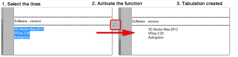
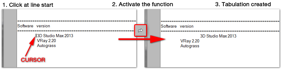
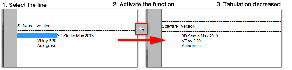
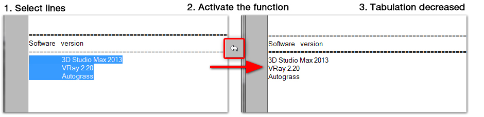
| How to - TAB contents |
|
|
| How to- Create a Numbered List |
|
|
|
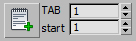
 activate/deactivate numbered list function activate/deactivate numbered list function
- TAB: tabulation value from the left margin of the main text window
- start: first index of the list
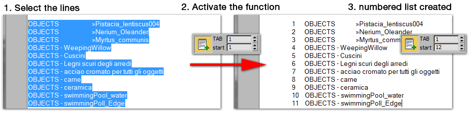
To create a numbered list activate the function pressing the button and each time that "enter" is pressed on the keyboard, a new line with a progressive index will be added into the main text window.
To change on the fly the index counter of the list or the tabulation, increase or decrease the values of the spinners "TAB" and "start".
To number simultaneously multiple lines into the main text window, if the button is pressed, deselect it, select the lines, set the spinners "TAB" and "start" and then press again (refer to the following example)
|
|
| |
|
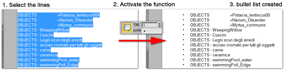
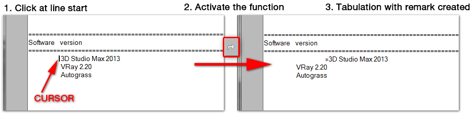
| How to - Create a Bullet List |
|
|
|
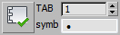
 activate/deactivate bullet list function activate/deactivate bullet list function
- TAB: tabulation value from the left margin of the main text window
- symb: the symbol used for the list
To create a bullet list activate the function pressing the button and each time that "enter" is pressed on the keyboard, a new line with a bullet symbol will be added into the main text window.
To change on the fly the symbol of the list or the tabulation, increase or decrease the values of the spinners "TAB" and digit by keyboard a new symbol into the text field "symb".
A list of special symbols and chars is available pressing  . Refer to the symbols window to learn how to populate the text field "symb" with special symbols and chars. . Refer to the symbols window to learn how to populate the text field "symb" with special symbols and chars.
To add bullets simultaneously to multiple lines into the main text window, if the button is pressed, deselect it, select the lines, set the spinners "TAB" and "start" and then press again (refer to the following example)
|
|
| |
|
| How it works - Find and Replace words window |
|
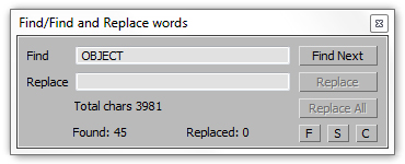 |
- Replace: replace the highlighted word
- Replace All: start to search and replace all the occurrences of the word typed into the text field "Find"
- F: find and enumerates all the occurrences of the word typed into the text filed "Find"
TIP
This function is suitable to be used for code developing to count the number of occurrences of a key word; cut and paste into the main text window the content to analyze and start the function pressing button "F"
- S: start a new search from the first document line and reset the counters "Found" and "Replaced"
- C: activate the chars count function including blank chars and spaces.
|
|
| |
|
| How it works - Symbols window |
|
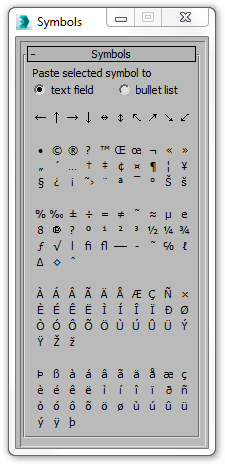 |
To open this window press
To insert a symbol into the main text window select "text field" and press the desired symbol.
To insert a symbol into the text field "symb" of the bullet list select "bullet list" and press the desired symbol. |
|
| |
|
| How it works - Convert selection |
|

|
a > A: convert selection to upper case
A > a: convert slection to lower case |
|
| |
|
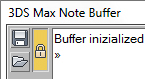
| How it works - Note Buffer |
|
|

|
Note Buffer is an extra text window to use for:
- load extra text contents from a .txt file
- past text from main text window
- use as buffer to store complex not undoable actions performed into the main text window (see below)
Each action performed automatically from the script, will be stored into Note Buffer with a remark (example 1).
 open/close Note Buffer open/close Note Buffer
 Press this button to automatically copy the selected text from the main text window to Note Buffer before one of the following operations is executed (example 1): Press this button to automatically copy the selected text from the main text window to Note Buffer before one of the following operations is executed (example 1):
- TAB INCREASE
- TAB DECREASE
- NUMBERED LIST
- BULLET LIST
- TO UPPER CASE
- TO LOWER CASE
 Press this button to copy the selected test from the main text window to Note Buffer (example 2). Press this button to copy the selected test from the main text window to Note Buffer (example 2).
 Save Note Buffer text content as .txt file Save Note Buffer text content as .txt file
 Open a .txt file into Note Buffer Open a .txt file into Note Buffer
 Link size and position of Max Note Buffer window to main text window. Link size and position of Max Note Buffer window to main text window.
|
| |
How it works - Note Buffer auto backup file |
| |
On close, Note Buffer window will save his content as .txt file into the same folder of the last saved file from the main text window with the name buffer_autoSave.txt.
It is not possible to disable this auto save function. |
| |
|
| |
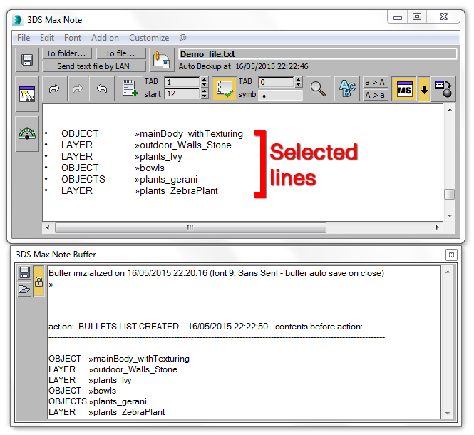
How to - automatically copy contents to Note Buffer - example 1 |
| |
With the button  pressed, the user has selected the highlighted lines to made a bullet list; before the creation of the bullet list, the selected contents have been copied to Note Buffer with a remark and they can be reused in case of need. pressed, the user has selected the highlighted lines to made a bullet list; before the creation of the bullet list, the selected contents have been copied to Note Buffer with a remark and they can be reused in case of need.
When is pressed, the same action will be automatically performed by 3DS Max Note for the following operations only for the selected text into the main text window: TAB INCREASE, TAB DECREASE, NUMBERED LIST, BULLET LIST, TO UPPER CASE, TO LOWER CASE. |
| |
 |
|
| |
|
| |
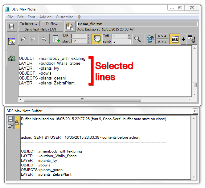
How to - automatically copy contents to Note Buffer - example 2 |
| |
With the button pressed, the user have selected the highlighted lines and after has pressed ; the selected contents has been copied to Note Buffer with a remark and it can be reused in case of need. |
| |
 |
|
| |
|
| How it works - Linear equations calculator |
|
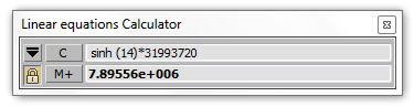
Compact version
|
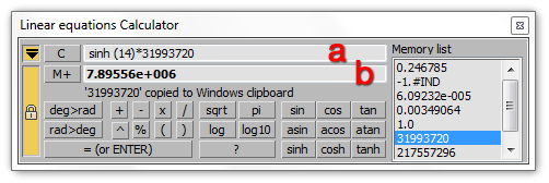
With this calculator is possible to solve complex linear equations
ex. 2+(45*4)-sqrt(34)+log10(23)+(sin(45)/tan(79))
The calculator has 2 editable text areas that work as displays.
The display a can be used uniquely to type the operations to execute and the result will be shown by display b.
The display b can be used in the same way of the display a, but when the operations are executed, the result will overwrite the operations.
TIP
Use the display b to execute simply operations as the standard Windows Calculator.
 to switch to the compact version of the calculator to switch to the compact version of the calculator
 to link the calculator positioning to the 3DS Max Note position to link the calculator positioning to the 3DS Max Note position
 to clear display a contents to clear display a contents
 to copy the results from the display b to Memory List to copy the results from the display b to Memory List
Memory List: this list can contain unlimited values; a double clicking an item of the list will append the contents to the display a and will copy it to the Windows Clipboard to be pasted into other applications (refer to image). |
| |
|
| |
|
|
|
|
| |
|
|
|
| |
|
| Overview |
|
| |
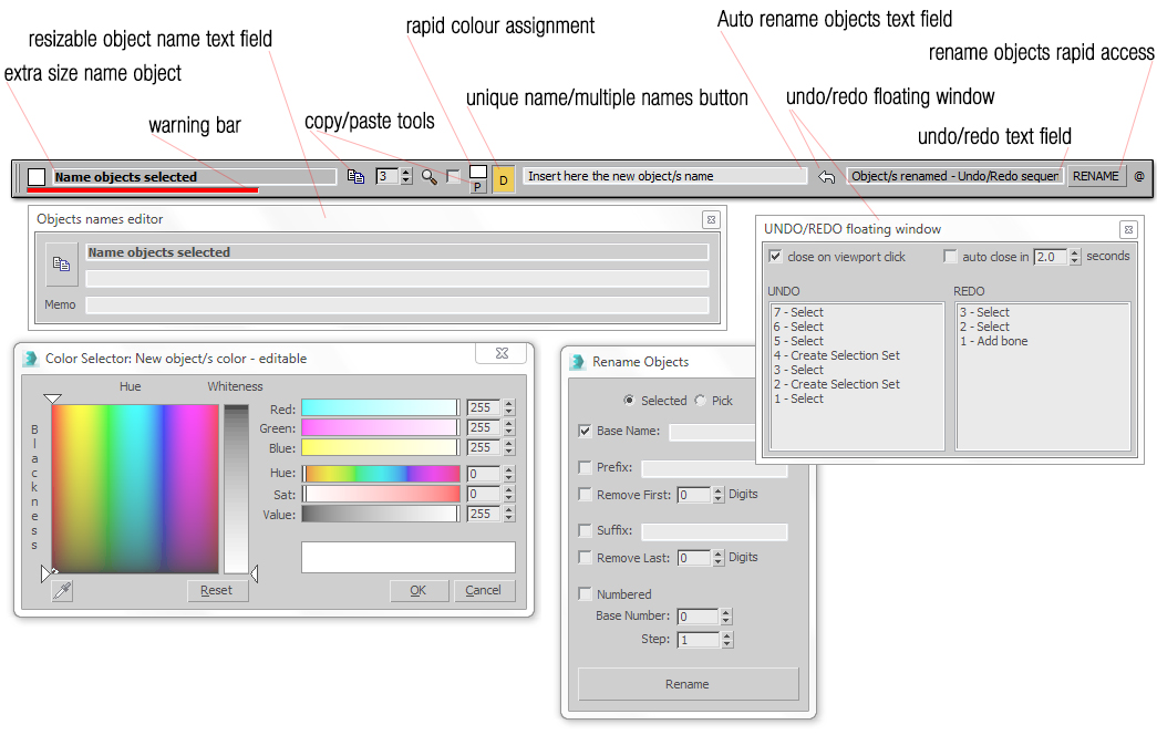
| This script will open an auto resizable bar that is possible to place on top of 3DS Max window; it contains the following tools to enhance the following 3DSD Max functions: Extra size object name text field, Warning bar, Auto rename objects text field, Unique name/Multiple names button, Floating UNDO/REDO window, UNDO/REDO text field and Copy and paste tools. |
| |
| |
 |
| |
|
| How to install |
|
|
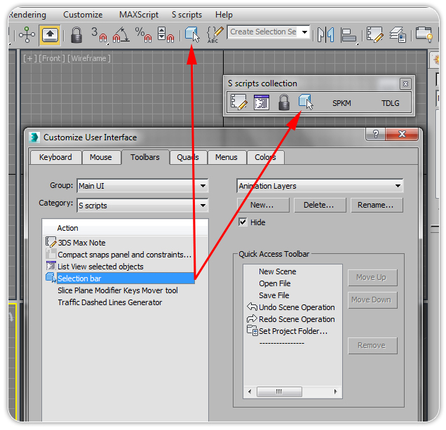
- Drag the file from the folder where it is located directly into one of the 3DS Max viewports; the script will automatically create a category named "S Scripts"
- Go to CUSTOMIZE > CUSTOMIZE USER INTERFACE > TOOLBARS and into the sub menu CATEGORY from the related drop down list select "S Scripts"
- Fom the list ACTION select the item named "Selection bar" and drag it directly to 3DS Max Main Tool Bar and a button with an icon will be added to it.
For more detailed instructions on how to install a script click here.
For more detailed instruction on how to create a new tool bar click here.
|
 |
|
| |
|
| How it works |
|
 |
| |
| |
| |
|
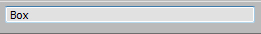
- object name: into this text field it is displayed the name of the selected object or the objects number of a multiple objects selection, solving the problem of the extremely small standard 3DS Max name field; text content is not editable, but it is selectable. To edit object name please refer to auto rename object/s text field.
The size of this text field will be resized proportionally to the screen width: bigger is the screen resolution and bigger will be its size.
TIP
When more objects are selected, into text area will be displayed the exact number of the selected objects; if a group is selected and it contains 3 objects, plus a nested group with other 6 objects, the text area will display this message "9 OBJECTS SELECTED"
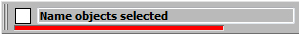
- Warning bar: the red color of the bar will indicate if the selected object or multiple objects selection have been transformed by tools MOVE, ROTATE or SCALE
TIP
it is extremely useful to prevent accidental transformations (ex. accidental translation of the camera or objects when the user click into a viewport to switch the view port)
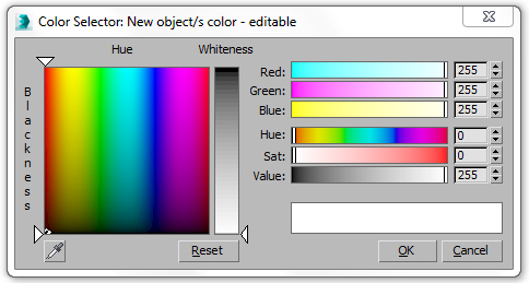
- colour selector: shows the colour of the selected object: it is not editable; in case of multiple selection objects it will disappear
|

|
- name copy: on press will copy the name of the selected object from the object name field to Windows Clipboard.
TIP
this feature is useful to paste the object name into an external spread sheet, to compile a database.
|

|
- number of digits: this spinner indicates the number of digits to use in case of multiple objects renamed; please refer to auto rename object/s text field for details and to example 1
|

|
|
|
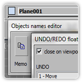
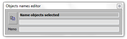
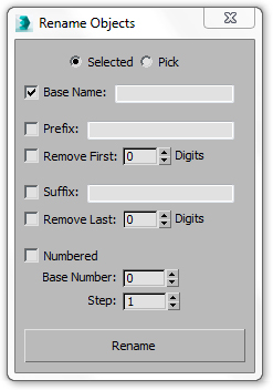
- Objects name editor: an extra horizontally resizable window to display extra long objects names; the result of the operations made by Objects name editor, are influenced by the Unique name/Multiple names button
TIP
extremely useful to work with CAD models imported in 3DS Max with long names generated from exporting processes or laser scanning software; refer to example1
 name copy: this button has the same function of the name copy button name copy: this button has the same function of the name copy button
- Memo: it is an empty text field to take notes for extra details to add to objects name
|

|
|
 
|
- Unique name/Multiple names button: by this button the user can assign to the selected objects or to a multiple objects selection a unique or a duplicate name ; extremely useful to create an objects name database without duplicated instances, to use to develope code into an external software or code editor. Please refer to example1 for its use
|
|
- Auto rename objects text field: without use the standard 3DS Max rename tool window, is possible to assign multiple objects names with an incremental index. Please refer to example1 for its use
|

|
|
|
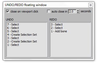
- Undo/Redo floating window: it contains a list of the redo and undo actions, readable without select the default Undo/Redo arrows
- Close on viewport click: when checked, on user click into one of the active 3DS Max view ports, the window will be closed
- Auto close in...: when checked, it defines the time in seconds to automatically close the window.
If both options are unchecked, the window will be available on the screen: press the icon  to close it. to close it.
|
|
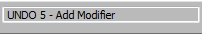
- UNDO/REDO text field: to read in real time the undo/redo actions performed without open the default 3DS Max undo/redo list
|

|
- Rename: on press open the default 3DS Max tool to rename objects
|
| |
|
|
|
| How to - multipurpose selection bar - example 1 |
|
 |
|
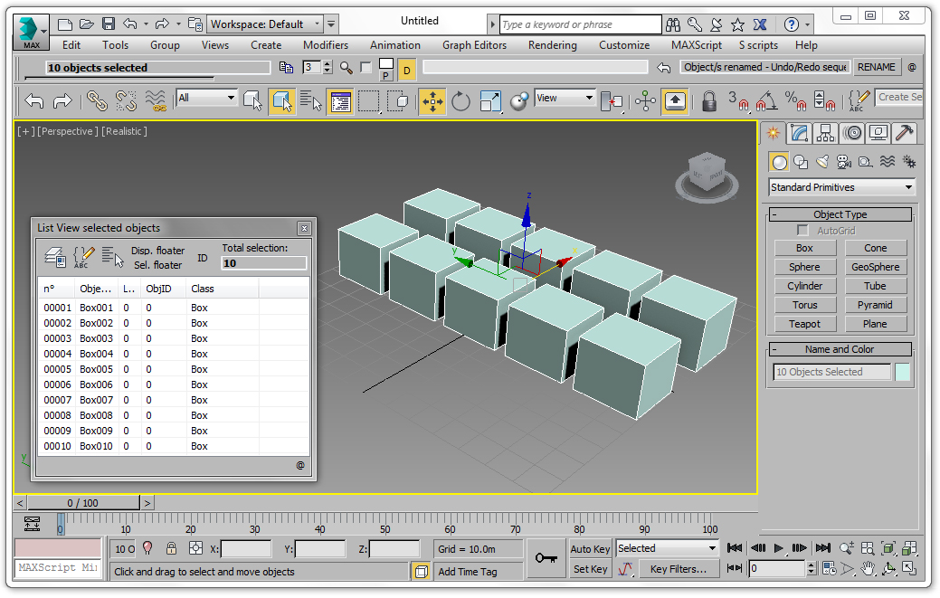
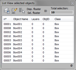
TO DUPLICATE THE OBJECTS' NAMES INTO THE SCENE
The scene into the above example is composed by 10 boxes with different name, assigned by default during the clone process. To rename the boxes from "Box006" to "Box010" duplicating the existing names (Box001...Box005):
- select the boxes (the selection order will influence the naming sequence)
- Activate the option "Duplicate names"
- set the spinner number of digits to 3
- Enter the following name into the auto rename objects text field
 and press enter and press enter
This will be the final result with the duplicated names:
|
|
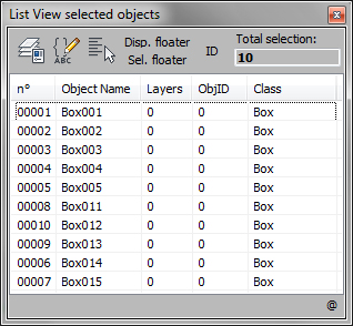
TO ASSIGN A UNIQUE NAME TO THE OBJECTS INTO THE SCENE
With reference to the scene above composed by 10 boxes with different names assigned by default during the clone process., to rename the boxes from "Box006" to "Box010" without duplicate the existing names:
- select the boxes (the selection order will influence the naming sequence)
- Activate the option "Unique name"
- set the spinner number of digits to 3
- Enter the following name into the auto rename objects text field and press enter.
This will be the final result without duplicated names:
|
| |
It is possible to execute the same procedures opening by the maximize button the Objects name editor
|
| |
|
| |
| |
|
|
| |
|
| How to install |
|
- Drag the file from the folder where it is located directly into one of the 3DS Max viewports; the script will automatically create a category named "S Scripts"
- Go to CUSTOMIZE > CUSTOMIZE USER INTERFACE > TOOLBARS and into the sub menu CATEGORY from the related drop down list select "S Scripts"
- Fom the list ACTION select the item named "List view selected objects" and drag it directly to 3DS Max Main Tool Bar and a button with an icon will be added to it.
For more detailed instructions on how to install a script click here.
For more detailed instruction on how to create a new tool bar click here.
|
 |
|
| |
|
| How it works |
|
|
|
|
|
List view selected objects is a dockable window that collects all the 3DS Max selection methods and a table that display some properties for the selected objects.
|
| |
| |
|
| |
|
|
|
|
| |
|
| Overview |
|
This tool has been developed to speed up the animation process for architectural phasing when a repetitive sequence is required (ex. phasing animation for skyscrapers, steel frames structures, etc.). It allows the user, with only one action, to shift the animation keys of the slice planes modifiers applied to different geometries with an incremental or uniform value: the translation can be serialized by a selection order or by objects names. |
| |
|
|
|
| How to install |
|
- Drag the file from the folder where it is located directly into one of the 3DS Max viewports; the script will automatically create a category named "S Scripts"
- Go to CUSTOMIZE > CUSTOMIZE USER INTERFACE > TOOLBARS and into the sub menu CATEGORY from the related drop down list select "S Scripts"
- Fom the list ACTION select the item named "List view selected objects" and drag it directly to 3DS Max Main Tool Bar and a button with an icon will be added to it.
For more detailed instructions on how to install a script click here.
For more detailed instruction on how to create a new tool bar click here.
|
|
|
| |
|
| How it works |
|
|
| |
This script will work properly if he user has not changed the slice modifier name into the stack (see the how to section); if more slice modifiers are applied to a single object, the script will shift the animation keys only of the one at the top of the list and will ignore the other ones. |
| |
|
 |
- Move by: the shift amount of animation keys for the slice planes modifiers to apply to the selected objects; this value can be positive or negative
- Apply by objects name: the shift sequence for the animations keys of the slice plane modifiers applied to the selected objects will be executed by objects name
- Apply by selection order: the shift sequence for the animations keys of the slice plane modifiers applied to the selected objects will be executed by selection order
- Move with incremental translation: starting from the first objects into the selection, an incremental translation of the animation keys for the slice plane modifiers will be applied (if "move by= 10" and 3 objects with the slice planes modifiers applied and animated are selected, the first object into the selection will have a translation of the animation keys of 10 frames, the third one of 30 frames); see the how to section for examples.
- Move with uniform translation: to all the objects into the selection, a uniform translation of animation keys for the slice plane modifiers animated will be applied (if "move by= 10" and 3 objects with the slice planes modifiers applied and animated are selected, all the objects into the selection will have a translation of the animation keys of 10 frames)
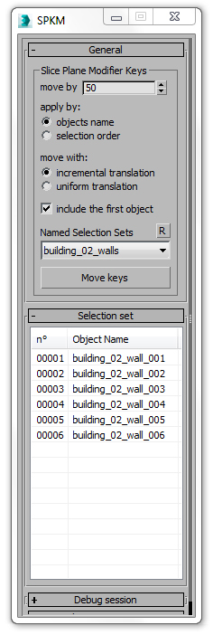
- include the first object: (default off) when on, the first object selected will be considered into the transformation process, otherwise it will be excluded
TIP
The script will consider as first object:
- the "first selected object" if the "apply by" section is set to "selection order"
- the first object in alphabetical order into the selection if the "apply by" section is set to "objects name"
- Named selection set: the user can create selection sets to easily select geometries and apply the transformations; press to update the list contents
- Move keys: press the button to apply the transformations
- Selection set: it is a list with the selection order made by the user; it is possible to reorder the elements into the list clicking on the columns headers, to arrange by name or selection order the elements, so to understand the right sequence to which the transformation will be applied
- Debug session: after the shift of the keys has been applied to all the objects, the user can check into this rollout if all the processes have been executed correctly and eventually which kind of errors the script has generated for each single geometry selected.
|
| |
|
|
|
| How to - example 1 - create a serialized animation |
|
This tutorial will show how to serialize an animation of the slice plane modifiers.
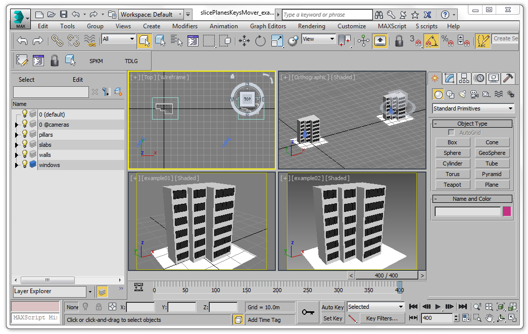
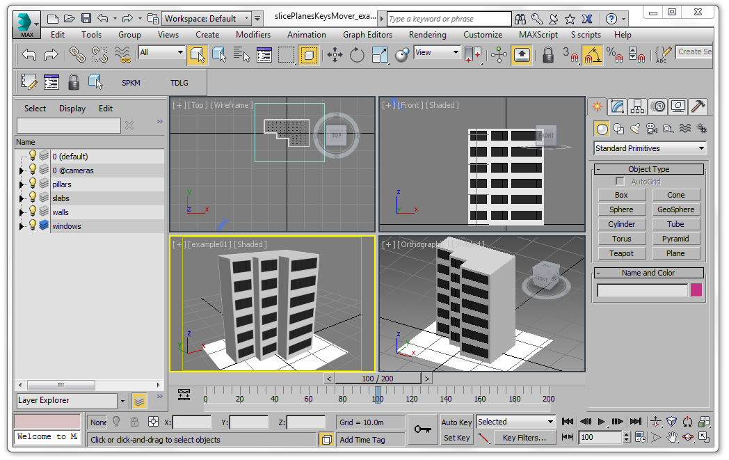
Open the file help\scenes\ slicePlanesKeysMover_example1.max (version 3DS Max 2015).
In the viewports there are two cameras (example01 and example 02): the building into camera example02 (named building_02) is a copy of the building into cameras example01 (named building_01); to see them drag the timeline slider to the frame 400. |
 |
| |
|
| Step 1 |
|
|
|
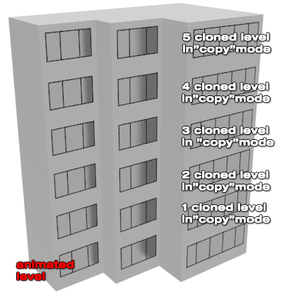
This is the most common case for architectural phasing animation, where the building levels have the same structure (slabs, walls, frames, pillars, etc.).
For the building_01 only the ground level has been modelled and animated , more precisely only the geometries:
- building_01_slab_001
- building_01_pillar_001
- building_01_wall_001
- building_01_window_001
while all the others levels have been cloned in "copy mode"; dragging back and forward the timeline slider, will be possible to appreciate that all the levels have the same animation.
Following the next steps we will made an animation, where all the building elements will be serialized to match the constructive phasing programme. |
 |
|
| |
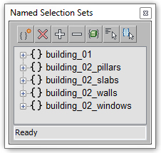
A good practice to use this script is to create "named selection sets" to easily select the objects into the scene.
Click on  to open "Named Selection Sets" window: it will contains the sets organized by categories to animate. to open "Named Selection Sets" window: it will contains the sets organized by categories to animate.
Open the script and press the button  to refresh the list. to refresh the list.
Before serializing the animation, hide the layers pillars, walls and windows: the results of the operations in progress will be more evident.
|
  |
|
| |
|
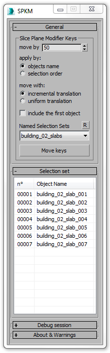
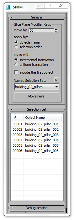
From the drop down list select "building_02_slabs" and configure the script window as into the image.
Press the button "Move Keys" to apply the transformations and drag back and forward the animation timeline to visualize the result.
With the "move by" spinner sets to 50, the transformation applied by "objects name" with "incremental translation" and the first object "building_02_slab_001" excluded from the transformation, this is the result:

The new animation keys are:
1 building_02_slab_001 (original interval 0f 25f) new interval 0f 25f -> excluded from transformation
2 building_02_slab_002 (original interval 0f 25f) new interval 50f 75f -> (1*50=50)f (50+25=75)f
3 building_02_slab_003 (original interval 0f 25f) new interval 100f 125f -> (2*50=100)f (100+25=75)f
4 building_02_slab_004 (original interval 0f 25f) new interval 150f 175f -> (3*50=150)f (150+25=175)f
5 building_02_slab_005 (original interval 0f 25f) new interval 200f 225f -> (4*50=200)f (200+25=275)f
6 building_02_slab_006 (original interval 0f 25f) new interval 250f 275f -> (5*50=250)f (250+25=275)f
7 building_02_slab_007 (original interval 0f 25f) new interval 300f 325f -> (6*50=300)f (300+25=375)f
Open the "Debug session" to check the results.
We will repeat the same operations for the other elements: pay attention to respect the set up of the script!
|
 |
|
|
| Step 2 |
Step 3 |
Step 4 |
From the drop down list select "building_02_pillars" and configure the script window as into the image.
Press the button "Move Keys" to apply the transformations and drag back and forward the animation timeline to visualize the result. |
From the drop down list select "building_02_walls" and configure the script window as into the image.
Press the button "Move Keys" to apply the transformations and drag back and forward the animation timeline to visualize the result. |
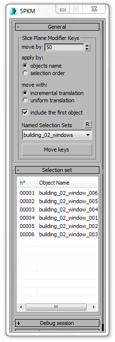
From the drop down list select "building_02_windows" and configure the script window as into the image.
Press the button "Move Keys" to apply the transformations and drag back and forward the animation timeline to visualize the final result. |
|
|
|
 |
 |
 |
|
| |
| How to - example 2 - translate uniformly an animation |
|
This tutorial will show how to translate uniformly the animation keys of the slice plane modifiers.
The example will look extremely easy, but with complex projects, with a lot of 3D elements with a slice plane modifier applied, it will make much easier and safe this operation.
Open the file help\scenes\ slicePlanesKeysMover_example1.max (version 3DS Max 2015).
In the viewports there is the camera example01: to see it drag the timeline slider to the frame 100. |
| |
 |
| |
| A good practice to use this script is to create "named selection sets" to easily select the objects into the scene;
Click on to open "Named Selection Sets" window: it will contains the set building_01 that contains all the objects with an animated slice plane modifier.
Open the script and press the button to refresh the list.
From the drop down list select "building_01": all the animated objects are selected and the time line will look as the one into the image; all the selected elements are animated from frame 0 to frame 100: we want to translate uniformly all the keys of 50 frames.
|
 |
With all the objects selected configure the script windows as into the image and press the "Move Keys" buttons: all the animation keys will be translated uniformly of 50 frames.
The spinner "move by" accepts negative values too, to translate backward the animation keys.
Check the "Debug Session" too.
|
 |
Selecting by the "Named selection sets" the set building_01, the animation time line will look as into the image.
|
 |
|
| |
|
| |
| |
|
|
|
| |
|
| How to install |
|
- Drag the file from the folder where it is located directly into one of the 3DS Max viewports; the script will automatically create a category named "S Scripts"
- Go to CUSTOMIZE > CUSTOMIZE USER INTERFACE > TOOLBARS and into the sub menu CATEGORY from the related drop down list select "S Scripts"
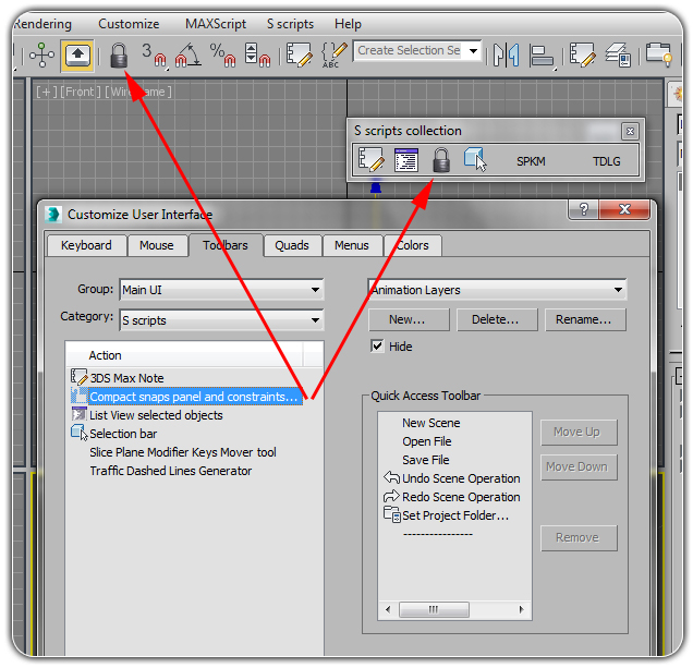
- Fom the list ACTION select the item named "Compact snaps panel and constraints" and drag it directly to 3DS Max Main Tool Bar and a button with an icon will be added to it.
For more detailed instructions on how to install a script click here.
For more detailed instruction on how to create a new tool bar click here.
|
 |
|
| |
|
| How it works |
|
|
| |
| |
| |
| |
| |
| |
| |
| |
| |
| |
| |
| |
| |
| |
| |
| |
| |
| |
| |
| |
| |
| |
| |
| |
| |
| |
| |
| |
| |
| |
| |
| |
| |
| |
| |
| |
| |
| |
| |
| |
| |
| |
| |
| |
| |
| |
| |
| |
| |
| |
| |
| |
| |
| |
| |
| |
|
| |
| |
| |
| |
| |
| |
| |
| |
| |

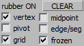 this section will indicate the state of the snap options: check the desidered option to activate it
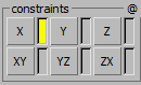 on pressing 3DS Max will switches between the selected constraints options.